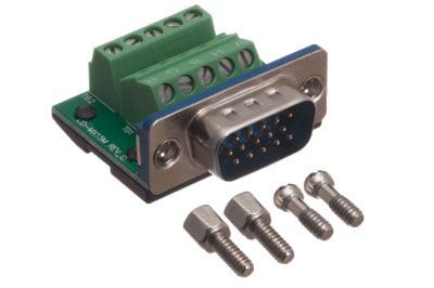
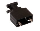
These MaxBlox Terminal Block Panel Mount Connectors are used to terminate any cable in the field with a custom pinout in a fast and easy way. This solderless connector fits into installs where depth is a problem, and it provides a reliable connection for all applications with no special tools. With its sled-shaped bottom, this connector easily slides and snaps into place in the MaxBlox Hood. These connectors are made with high-quality materials to ensure durability and a long life.
Terminal Block: VGA Field Termination Pinout Instructions
The back of the terminal block consists of two horizontal rows: the top is for conductors; the bottom for the ground. The five columns are labeled V H B G R.
The labels correctly correspond to the colors of the mini-coax cable: red to R green to G and blue to B. Screw the center conductor of the corresponding color into the top row and the shielding into the bottom row.
The cable will need to be stripped approximately one inch in order for the shield to reach the ground on the bottom row.
The H and V refer to 'Horizontal Sync' and 'Vertical Sync.' The Horizontal Sync corresponds to Pin 13 and the Vertical Sync to Pin 14. Usually the H is a small white wire and the V is a small black one but for long or hidden runs you may need to find Pins 13 & 14 with a tester. Screw the conductors into the corresponding sockets on the top row.
Depending on the type of cable the H & V syncs may each have a ground similar to the R B & G cables; in which case ground them the same as the colored wires. Or there could be a separate shared ground wire. In that case screw it into the ground socket of either the H or V columns. It does not matter which socket because the H & V Syncs share a common ground. You can even test the Maxblox and note that the pins are tied together.
Terminal Block Rear Diagram
V(Vert Sync) Pin #14
H(Horiz Sync) Pin #13
B(Blue Coax) Pin #3
G(Green Coax) Pin #2
R(red CoaX) Pin #1
Sync Ground
Pin #10
Sync Ground
Pin #10
Blue Ground
Pin #8
Green Ground
Pin #7
Red Ground Pin #6
VGA Pinout
Pin
Name
Direction
Description
1
RED
→
Red Video
2
GREEN
→
Green Video
3
BLUE
→
Blue Video
4
RES
RESERVED
5
GND
Ground
6
RGND
Red Ground
7
GGND
Green Ground
8
BGND
Blue Ground
9
KEY
Key (No pin)/ Optional +5V output from graphics card