DB9 Connector Pinout


When building or repairing DB9 cable assemblies many customers request a DB9 connector pinout reference drawing in order to determine where each conductor of the cable should be terminated to. There are several primary types of DB9 connector pinout schemes that we will review in blog post.
DB9 Connector Pin Locations
First, we will take a look at the DB9 connector pin locations for a male and female DB9 connector. Note the orientation of the connector where the short side of the shell is located on the bottom and the longer side is on the top.
There are several DB9 connector Pinout schemes to address different standards and technologies. Here we take a look at two of the predominantly used configurations.
DB9 connectors used for RS232 communications
DB9 connectors have long been used in serial communications to attach peripherals to PCs. With the advent of USB connectors, DB9 is no longer the connector of choice for this function but there are still legacy devices using DB9 connectors for RS232 connectivity.

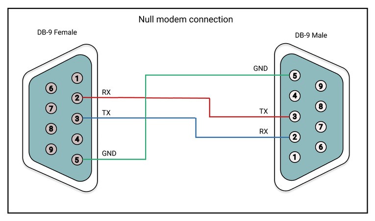
Another use for DB9 connectors is with Null modem communications.
A null modem DB9 serial cable (frequently called a crossover cable) is used to connect two Data Terminal Equipment (DTE) devices together without the use of a Data Circuit Equipment (DCE) device in between. For this to work, the transmit (TXD) and receive (RXD) pins on one of the serial connectors are flipped.
In addition to the DB9 connector pinouts we just reviewed, there are many custom DB9 pinout configurations used by OEM’s to performance a variety of communications and control functions.
We hope you found this DB9 Connector Pinout blog post helpful.